3D Printer Electronics Enclosure
Meta Code and Eng DK30 Fall 2023 0 0
Description
I want to rewire my Ender3 3D printer and house the electronics in a new enclosure. Most electronics are frustratingly bolted underneath the printer frame so you have to upend the printer to access them. The goal is to move the electronics away from the frame and into an easy-to-access enclosure.
Recent Updates
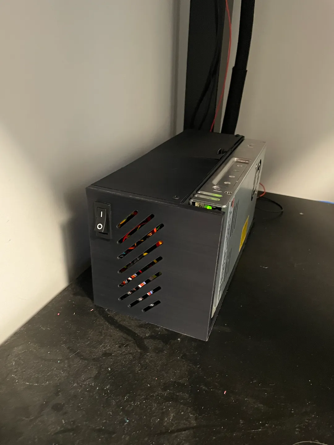
A couple of progress shots. All of the cables pass through the rear ports on the enclosure. I found a cable that a cat chewed through that will need to be replaced. This is a good reminder to think about cable shielding. i would happily wrap it all up in a protective sleeve, but not all of it is the same length. This will take some thought on how to tackle.


The goals for week 3 will need to change, the biggest being coming up with a solution for the power supply. My main goals are: 1. have the power supply mounted to the rest of the electronics in some way. 2. Consider a silent fan upgrade for the PSU, 3. bonus, consider getting a buck converter to power the raspberry pi from the PSU (still via the USB to maintain the safety regulators built into the Pi).
I have been considering pivoting to a new enclosure with mounting for the PSU. There is this design for example:
But my other option is to stay the course and adjust what I already have. Currently I am leaning this way to avoid backtracking on progress. I am thinking of basically sitting the electronics enclosure on top of the power supply assembly, maybe bolting them together. I want the whole assembly to be easy to move if I ever need to move the printer.
Right now I’m going to route more cables through the existing enclosure. Picture update to follow. Ideally I would identify at least 50% of the cables that need replacements so I can work towards that.
Thanks to this article I was able to connect my printer mainboard to the raspberry pi without a USB cable, instead going over serial. This is important because the 3D printed enclosure I’m using routes the normal pi-Printer USB connection outside the housing, and it’s a bit ugly/untidy.
Specifically, I have an SKR Mini E3 v2 and Raspberry Pi 4B. I connected the TFT serial to the Pi serial header pins. I didn’t need to adjust my mainboard firmware, thanks to the TFT serial being programmed in by default as the first serial connection.
Next I will post some revisions to the weekly goals now that the progress has progressed.
Yesterday was a lot of good progress. Starting with removing the electronics from the frame, and ending with getting them with an initial fit into the 3D printed enclosure. The best part? That everything still worked afterwards! This wasn’t a guarantee since I had to unplug some things and even re-terminate some connections.
Unmounting everything (note the Pi right angle USB power fits now thanks to my remix of the original model):

Here is the enclosure front, once the electronics are installed this is how clean it should look.
Link to more photos of the progress of moving everything. https://imgur.com/a/TUBFCaE
The last couple of days I have landed on a specific 3D model for the enclosure and printed it, which was a remix of Mr Clowns model I linked last week. The remix made the mounting holes compatible with my aftermarket mainboard. I further remixed the model in Meshmixer to move the Raspberry Pi mounting, in an attempt to make room for my right angle USB C adapter for the power. Here is a screenshot of the modification I made to move all the Pi features over (I also deleted one of the main board columns, I don’t need all of them).
This was the problem, my right angle adapter did not clear the wall.

This was my attempted solution by moving the mounting holes away from that wall. I believe there is more to do with this remix, I will post a link to it later in this project.

Use this link to see the images if picture links are breaking: https://imgur.com/a/lAbrBQ0 .
An acknowledgment of EMI:
Because I’m changing the routing of the wires I want to consider things like interference and noise. The printer main board has 3 sets of power wires coming in and out of it (power in, bed heater out, hot end heater out). Putting those 6 power lines in parallel with data lines seems theoretically to be a bad idea. There is also stepper motor power, although it is unclear how much that contributes to EMI or not.
I’ve been researching the topic of interference as it appears in 3D printers as well as observing how the existing set up routes cables.
Example post about user getting video distortion from their raspberry pi camera from a stepper motor. https://www.reddit.com/r/ender3/comments/hj943z/stepper_motor_wires_causing_interference_on_a/
Wiki discussing 3D printer EMI and end stops (which are simple data lines that need to be fairly precise). It also includes mitigation such as software/hardware debouncing: https://marlinfw.org/docs/hardware/endstops.html
I don’t have a conclusion about this yet, but I wanted to jot down some thoughts and good posts I found.
I have spent time researching different electronics enclosures, and I am gravitating towards this one by user “MrClown”. https://www.thingiverse.com/thing:3631413/remixes

This is a photo of the 3d model I posted last week, which showcases the “slide out” design that seems like it will make it super easy to access the electronics. I also like this users remake that attaches the box to the PSU unit (https://www.thingiverse.com/thing:5326041)

Looking at the first photo, it appears possible to rehouse the electronics without extending all of the wiring. This is very appealing, reducing the scope of my project but still accomplishing my core goals.
Speaking of those goals, I have a google spreadsheet of the existing wires. In case anyone wants to know these are all the wires I documented:
Description of Wire
- Stepper motor X (axis)
- Stepper motor Y
- Stepper motor Z
- Stepper motor E
- Hotend heater
- Hotend thermistor
- Auto Bed Leveling probe
- Hotend Fan
- Part cooling fan
- Bed heating
- bed thermistor
Starting with the current state of my printer: this my current printer setup in all it’s hacky, modded, glory. At this time everything is mounted to the frame. This includes:
- The screen
- Main controller board
- Raspberry Pi computer
- Power supply

The following is an example of what I want to do by showing the screen being relocated away from the frame and outside of an enclosure.

And lastly, an example of a 3D printable housing that will accommodate the electronics. Ideally I would like the power supply to be enclosed as well.
 Image from: https://www.thingiverse.com/thing:4501568/remixes
Estimated Timeframe
Nov 14th - Dec 14th
Week 1 Goal
- List out every existing wire and it’s purpose, label them
- Survey existing off-the-shelf cable kits for extension
- Find 3+ different 3d printable electronics housings
- Choose length of cable run (researching maximums for different components)
Week 2 Goal
- Choose a model for the electronics housing.
- Print 50% of the housing
- Source hardware needed for assembly
- Source at least 50% of the wires
Week 3 Goal
- Source 100% of the wires
- Print 100% of the electronics housing
- Assemble 50% of the housing
- Finish assembling housing, verifying that no more 3d printing will be needed until the project is finished.
Week 4 Goal
- Remove electronics from frame
- Lay out new wiring next to existing wiring, verifying the new wiring will match
- Swap wires for new wiring
- Run test print to verify installation was successful


